

IEEE Standards
ANSI/IEEE C37.04-19791
and ANSI/IEEE C37.010-19792
are the standards relating to the rating structure and application of circuit
breakers. There is no specific advice concerning low temperature. The standard
service conditions are covered in C37.041,
which includes altitude less than 1000m, and a temperature range of -30°C to
+40°C. Other features are covered as well, from seismic to frequency. There is
reference in C37.04.2.3.31
to low temperature as an unusual operating condition. And -60°C certainly is
unusual.
SF6 Circuit Breakers and SF6 Basics
SF6 has unique properties which render SF6 a nearly ideal media for arc interruption and dielectric strength. The dielectric strength is greater than any other known media at the same density. The reason lies in the relatively large physical size and mass. The molecular weight is 146. Nitrogen and Oxygen are 28 and 32 respectively. The size and mass help reduce the propagation of free electrons. SF6 also acts as an inelastic damper for collision mechanism. SF6 is in the same class as freons which all have excellent dielectric properties. SF6 has unusual thermal properties which contribute to its arc interruption. SF6 has intrinsically higher thermal conductivity at low temperatures. Figure 1, which is a plot of the thermal conductivity in Watts/cm2/K° of SF6 and N2 and temperature. The existence of this peak in conductivity results from a change of state of the gas. The disassociation requires a well defined amount of energy, much like the heat of vaporization. This enhances the thermal transfer at arc, helping reduce the arc temperature. Conversely in lower ambient the elements recombine and liberate this energy, transporting copious amounts of energy across the electric arc.
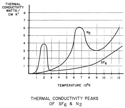
Figure 1
In other diatomic gases like O2 and N2, SF6
becomes conductive when ionized. SF6 remains
basically an insulator during the disassociation of the arc, further aiding the
dielectric and interruptive properties. The disassociation of SF6
produces Fluorine, the most electronegative element, at 3.95, in the periodic
chart (Figure 2).
This enhances the capture of free ions, and capturing free ions reduces
conductivity. As the temperature of the arc is reduced, Fluorine ions, with less
than 1 percent the mean free velocity of electrons, capture free electrons and
reduce the current density significantly. These two properties, high
electro-negativity which results in high electron capture, and high thermal
conductivity at relatively low temperatures, give SF6
its ‘made for electrical apparatus’ properties.
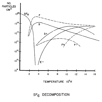
Figure 2
Although the gas is nearly ideal, it does have one major disadvantage. The main
disadvantage, from our perspective, is the relatively high liquefaction point of
SF6. Figure
3 The liquefaction occurs between -10°F and -30°F, depending on the
density (70psig to 95psig ranges found in circuit breakers manufactured today3)
of the SF6. Here we have somewhat conflicting
requirements; the need to extinguish the arc and provide dielectric strength,
and the physics of SF6. The higher densities
and pressures increase the liquefaction temperature, a very unsatisfactory side
effect. In locations where the wintertime temperatures fall below -10°F, for
even an overnight excursion, the manufacturer or user must provide supplement
means to maintain the SF6 above -10°F. Figure
4 Sometimes the choice is made to maintain the gas warmer to allow a
prudent reserve heat mass as a safety margin.
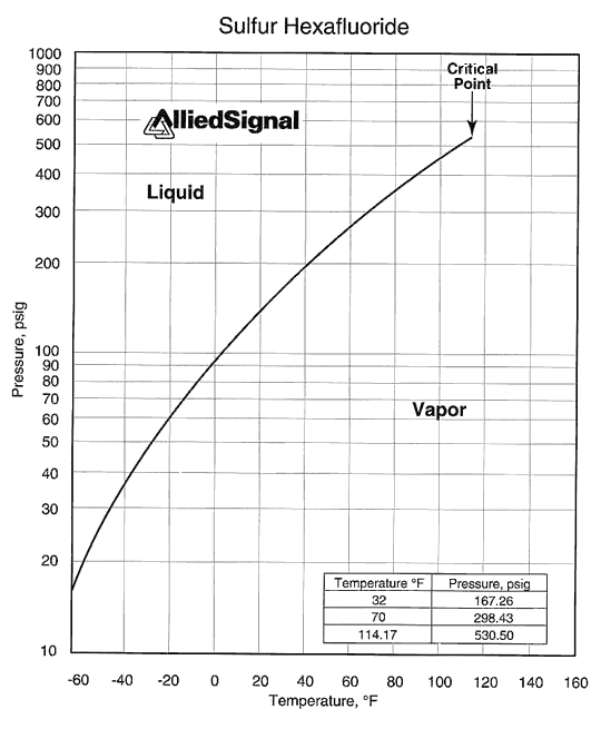
Figure 3
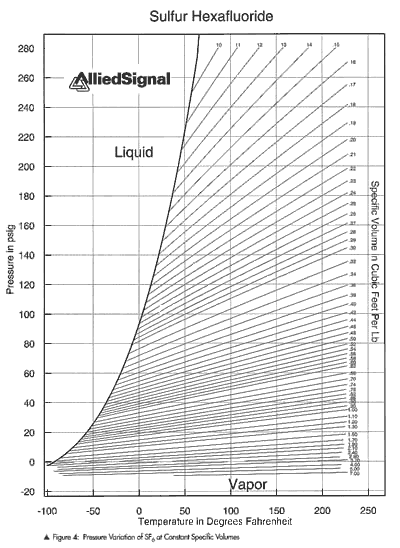
Figure 4
Reflecting on our operational experience, it
would appear that cold weather testing to date does not adequately reflect
environmental conditions. In many cases, Minnesota Power and other northern
climate electric utilities have provided the test laboratories for cold weather.
Incidents in February 1996
The normal learning curve for this apparatus and
problems associated with all the various styles are manageable, taken during the
normal course of maintenance. Operations and Maintenance help to clarify the
situation and the problems are remedied on a regular basis. Even with a few
alarms on an overnight temperature sag, after operators gain experience with the
thermal recovery of the tanks and density monitors, the situation is tractable.
However, in the period January 19 through February 2 our service territory
experienced temperatures in excess of -50ºC and several nights the temperature
sagged to near -60°C. On the morning of February 2, MP had 22 SF6
circuit breakers in alarm and three, 134L, 115MW and 762L, were locked out. The
three that were locked out were all at the International Falls 115/15kV
Substation. International Falls experienced -45°C that morning with a wind
chill of -80°C. MP has produced composite charts from U.S. Weather Service data
(5) of air temperature, average wind speed and nominal wind drill for three
locations in our service territory (see Figure 5).
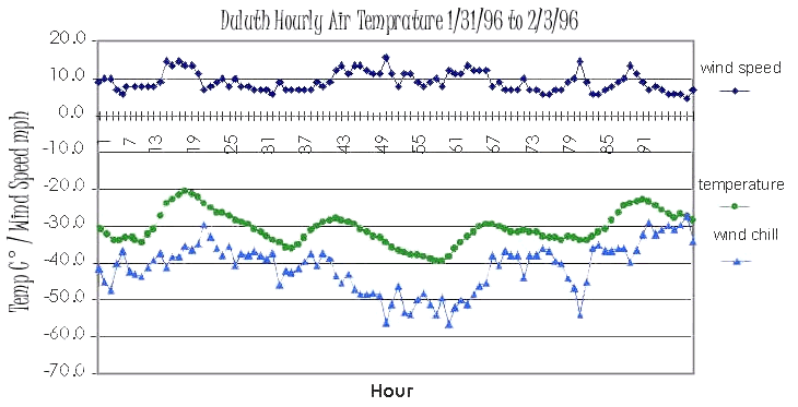
Figure 5
This station provides service to International Falls, Boise Cascade and the
surrounding area, and is the interconnection with Ontario Hydro at Fort Frances.
Any event which causes a transfer trip or breaker failure and cannot be cleared
at the site has serious consequences to customers. MP serves International Falls
and several smaller communities from this substation, as well as several major
customers. An outage at this time of the winter is very undesirable. A
disturbance on the line could have meant breaker operations at Little Fork/Running
230kV Substation. MP is relying at Little Fork 230kV Substation, as well, for SF6
breakers to operate.
To bring the International Falls substation back into service would have posed
severe hardships. All systems, because of the extremely low ambient and wind
chill, would cool quickly. Maintaining heat in the control house would have been
difficult. At temperatures below 45°F, the capacity of lead acid batteries is
reduced significantly from the nominal 77°F. IEEE C57.12.00-19934
section 4.1.2.2 and 4.1.2.3 outline the standard operating and design conditions
for transformers, and top oil temperatures or starting temperatures below -20°C
(-4°F) are not considered usual operating conditions. Unless specified and
designed to meet the lower starting temperatures, there may be restrictions on
operating and loading the transformer. During this period, Duluth experienced 13
days in a row where the minimum temperature was -10°F (-23.3°C) to -39°F
(-39.4°C)5.
What is the best means to start a transformer at these temperatures? Many of the
vendors recommend heating the core and coils. At the time of this event, MP was
not prepared for this scenario. MP does have procedures in place for supplement
heating should such an event occur.
Cold
Climate Problems
| Heaters | The existing heaters on many of the early designs were insufficient for a number of reasons. MP has changed or added heaters on approximately 25 SF6 circuit breakers. |
| Density Monitors | These presented another problem. Initial settings were incorrect. These devices also proved to be very difficult to set accurately and repeatability was a problem. |
| Sealing | First generation of SF6 circuit breakers Minnesota Power has in service also have leaking problems in cold weather. |
| SF6 Plumbing | Vendors have designed the SF6 fill and instrument lines on the circuit breakers to minimize cost and present a neat appearance, both of which are contrary to successful operation in cold weather. Usually, the design routes the piping neatly around supports to the control housing. Additionally, unless specified otherwise, the vendor uses smaller diameter flow lines. All the bends, restrictions and low spots add areas for condensation. The length and turns increase the fill and evacuation times of the tank. The low spots and length worsen the low temperature problem. More surface area is added and the low spots help the SF6 condense, and the smaller diameter leaves less thermal mass of SF6. |
| Station Service | Many of the SF6 circuit breakers were added to existing substations. The replacement of a single circuit breaker usually doesn’t warrant the close examination of the station service. Existing oil circuit breakers have, however, minimal heating requirements and, as a whole, their AC load is not significant. Some designs of SF6 circuit breakers have as much as 5kW to 7kW of connected load. In the case where several have been changed the upgrade of the station service probably may have been undertaken. In the situation where one per year is changed in a station, this has been frequently overlooked. Not only has the effect on the station service been missed, proper branch circuit sizing has been neglected. In several cases the effect has been as much as a 10 percent reduction in voltage at the breaker. The result is as much as a 20 percent reduction in wattage to the tank heaters. This results in further compromising the tank heating system. Unfortunately this condition was at the International Falls substation. In this case the circuit breakers were new but the AC branch circuit was undersized. |
Solutions
Operation
We began seriously to consider the effects of a
failure to operate and failure of a breaker. We quickly realized that, as the
breaker approached the magic alarm set point, the functionality of the circuit
breaker didn’t vanish. Rather, under reduced gas pressure, the capacity of a
circuit breaker to interrupt is diminished and a likewise similar condition for
the dielectric strength. In reality, at lockout the interrupting capacity on our
115kV class of circuit breaker was reduced about 10 percent 6. The SF6
breaker vendors of Minnesota Power indicate that their circuit breakers can
withstand system voltage at 15psig7,
and in some cases interrupt load current. Minnesota Power has procured
exclusively 40kA circuit breakers over the years. At 10 percent reduction in
interrupting capacity there still remains adequate margin, except at a few
sites.
We investigated the failure mechanism of SF6
circuit breakers. The vendors were not excited to discuss this condition.
Apparently, there has not been any factory testing to simulate this event or
anything similar. And most likely, failures have not been communicated to the
vendors. The case we proposed was a breaker with a gross breach of the tank so
the gas pressure was 15psig. Our concern was not for the final condition of the
breaker but the failure mode. We were concerned about the self destruction of
the tanks. Violent damage to the tank or porcelain could damage nearby apparatus
or harm nearby workers. We were not able to learn of any catastrophic or
eruptive failures of the designs in service at Minnesota Power. The worst case
we uncovered was a utility operating, under load, a SF6
circuit breaker with nearly atmospheric pressure in the tank. In this case there
was a complete burn through of the tank wall.
Minnesota Power does not envision operating, and has not operated, breakers in
this condition. However, we do plan to utilize fully the circuit breaker
capacity to avert a possibly more harmful situation. We are willing to assume
the risk of breaker damage or self destruction. Minnesota Power is prepared for
damage to a circuit breaker if necessary to protect apparatus or reduce the risk
of a more extensive outage. We are actively investigating means and methods to
avoid this situation. We believe a greater risk exists in having inoperable
circuit breakers during such an event. Warrantee claims were not a
consideration.
Physical
Changes
| Remove Block | On live tank circuit breaker at strategic locations we have disabled the block for tripping. The breaker still has alarms, but we do not inhibit tripping. |
| Temperature Recovery | Simply wait for the circuit breaker SF6 gas to recover after the temperature excursion. Normally, the temperature will recover sufficiently in two to four hours to reverse the alarm or lockout condition. This is the operating tactic that has been employed in the past successfully. Eventually, with other modifications we hope to eliminate this scenario. |
| Gas Mixtures | On live tank circuit breakers the remedial options to extend cold weather operation are few. The only option of which we are aware is to use a gas mix of SF6 and CH4. This is not an acceptable option for us. Mixing creates its own set of problems. |
| Retrofit Density Monitors | This was done initially on ten 115kV dead tank circuit breakers. MP worked closely with the vendor to install new or recalibrated density monitors. One problem we suspected was that confusion with Fahrenheit versus Centigrade occurred on the factory settings. A second problem was the repeatability of certain devices. All of these issues have been resolved. |
| Heaters | Part of the solution was to increase the heater size on many of the circuit breakers. There was insufficient heater wattage for our application and climate. |
| Seals, No Solutions | The cold weather and temperature extremes aggravate the operability of SF6 circuit breakers. A few first generation, two pressure SF6 circuit breakers have soldered connections on the bushings. The thermal cycling from -45°C to +35°C in our service area we believe is the chief cause. Minnesota Power has no unique solution for this situation. In the case that affects six 230kV older design two pressure SF6 circuit breakers, we are replacing them over a three year period. |
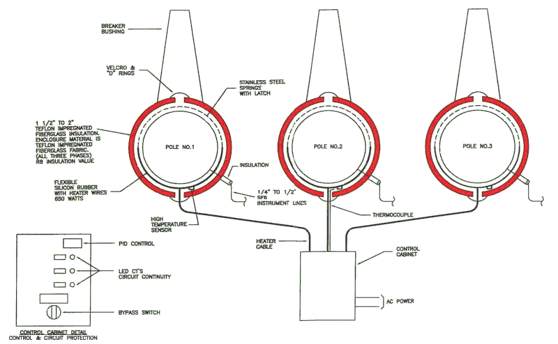
Figure 6
System
Design Parameters
Objectives
The heater is silicone rubber design, presently in use by OEM breaker vendors. The heater is designed with a very low watt density less than 2 watts/in2. In discussion with the supplier of the heating system, the threshold value to assure 20 operations of the heater was a maximum of 2.5 watts/in.26.
The insulation system is Teflon coated fiberglass fabric and Teflon impregnated fiberglass, custom designed and fabricated to various vendor tank designs. The material fabric and insulation have been used for 20 years in the petrochemical industry.The controls are manufactured as a complete system with PID controller with optional heater circuit continuity annunciation. Heater control is a type K thermostat mounted on the center phase. Each heater element is protected by an over temperature relay.
Results
| Installations | The system is installed at 10 sites at Minnesota Power, 20 circuit breakers total. These 20 circuit breakers include models from three vendors. One installation is at an adjacent utility. |
| Alarms and Lockouts | Although the winter of 1996-1997 was milder than 1995-1996, Minnesota Power experienced no alarms from any of the retrofitted breakers. |
| Test Site | The Minnesota Power Virginia 115/69/46kV Substation was selected as a test site for the new system. This is geographically near the center of the Minnesota Power service territory and can be reasonably expected to experience system average temperatures. |
| Temperature | The temperature is being monitored on two Minnesota Power breakers, nearly identical HVB™ 121kV, 2000 ampere 25L and 16L, serial numbers, h121a2058-205 and h121a2058-207, respectively. 16L breaker was the control breaker and the 25L had the Breaker Blankit™ system installed. The temperature is being collected with an Omega™ data logger that has the capability to be remotely downloaded. In this case, we are manually retrieving data from the unit. This unit has about 90 days available for storage. The installation was in place February 23, 1997, but not in time to collect any meaningful data from the winter. Minnesota Power will continue to monitor the test site throughout this winter. |
| Power Usage | Both circuit breakers are metered with identical single phase watt-hour meters. These are nominally used for residential metering on MP's system. Potential is taken from the existing AC power supply to the breaker. Clamp on type current transformers are used on the tank heater circuit. We expect the results to show a significant reduction in power use from our control breaker. Initially, the heaters are sized with respect to the insulation which provides a high insulating factor. The heaters sized this way are 80 to 85 percent of the original. |
The objective is to show that the heat maintenance system provides four benefits:
ANSI/IEEE C37.04-1979 - IEEE Standard Rating Structure for AC High-Voltage Circuit Breakers Rated on a Symmetrical Current Basis
[Back to Breaker
Blankit]
[Back to APS Main]
[Back to Metatech Main]